What is on-scalp MEG and how can we measure it?
Distance matters
Magnetic fields quickly drop off with distance from their source (roughly following a one-over-distance-squared relation). As a result, MEG is generally more sensitive to shallow sources, that is sources close to the scalp - and therefore also clsoer to the sensors - than deep sources. Conversely, this means that sensors closer to the head pick up stronger signals from the same source than sensors further away. In addition to having higher amplitudes, the magnetic field patterns are more focal closer to the source, which makes it easier to distinguish nearby sources but requires denser sampling (i.e., packing the sensors more densely) to capture the all the minute details of the magnetic field distribution. As a result, measuring closer to the head, so-called on-scalp MEG (osMEG) systems, can achieve higher sensitivity and spatial precision than conventional MEG systems that measure at approximately 2 cm distance.
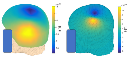
Figure 1: Simulated distribution of the radial magnetic field strength measured with conventional MEG approximately 2 cm from the scalp (left) and on the scalp (right).
Sensors - OPMs
Optically pumped magnetometers (OPMs) are a highly sensitive type of quantum enhanced magnetic field sensors. At their heart OPMs have a glass cell filled with alkali metal vapor (most commonly rubidium or cesium). At rest the spins or angular moments of the alkali atoms are randomly oriented (Figure 2-a). By shining laser light of a specific wavelength into the vapor, the alkali atoms can be pumped into a state where their atomic spins are aligned (Figure 2-b). This involves the atoms absorbing some of the light. Once all the atoms are pumped into the aligned state, the vapor stops absorbing the laser light and becomes transparent to it. When a magnetic field is applied, e.g., perpendicular to the laser beam, the atomic spins start to precess around the magnetic field (Figure 2-c), similar to what happens in MRI. As the atomic spins start to precess, i.e., leave their aligned state, they begin absorbing the laser light again. This in turn drives them back towards the aligned state. Precession and laser light absorption balance each other, resulting in a reduction of the transmission through the vapor cell. The speed of the precession, and as a result the change in transmission, depends on the strength of the magnetic field (assuming the laser power is fixed). We can measure the transmission with a photodetector behind the vapor cell.
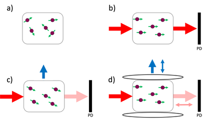
Figure 2: Schematic representation of an OPM. a) A vapor cell with rubidium atoms (purple) with randomly oriented spins (green arrows). b) Laser light (red arrows) shines into the cell and pumpes atoms into a state where all spins are aligned and do not absorb any more light. c) An external, transverse magnetic field (blue arrow) causes the atom spins to precess and absorb light. As a result less light reaches the photodiode (PD). d) A transverse, oscillating field is applied to the vapor cell using a Helmholtz coil. This results in a modulation of the transmitted light that can be detected at the photodiode and demodulated to obtain directional information.
There are a few important things to note here:
- In contrast to SQUIDs, OPMs measure the absolute field.
- The range is limited to low magnetic fields (typically few nT).
- The direction of the magnetic field is unknown. We assumed a magnetic field direction perpendicular to the laser beam but any direction that is not exactly parallel to the laser beam would create a precession.
The unknown magnetic field direction can be solved with a set of coils (e.g., a Helmholtz coil pair) that generate an oscillating magnetic field in the vapor cell that is perpendicular to the laser beam (Figure 2-d). The oscillating magnetic field (typically ~1kHz) modulates the signal in the direction of the oscillating magnetic field. If we demodulate the signal from the photodiode, we get the signal in the direction of the oscillating magnetic field. The demodulated signal roughly corresponds to the gradient of the original resonance-like signal with a linear dependence on the magnetic field close to zero.
One of the main mechanisms limiting OPM sensitivity, the so-called spin exchange relaxation, can be overcome by increasing the alkali pressure inside the vapor cell. Sensors using this method are called spin exchange relaxation free (SERF) and achieve the lowest noise levels but have a limited measurement range. To achieve optimum alkali vapor pressure the vapor cell is often heated to around 160 °C. Suspending the vapor cell in a vacuum encapsulation for thermal insulation reduces the - already small - power consumption and minimizes heating the sensor surroundings.
The measurement range of a SERF OPM can be increased in a similar way to SQUIDs, by creating a negative feedback loop, where a coil generates a magnetic field that opposes
the external magnetic field. The current through the coil that generates the opposing field serves then as the measurement signal. The magnetic field must be within the linear measurement range of the OPM when the negative feedback loop is activated. Alternatively, one must null the background field before engaging the feedback loop. This typically requires scanning the feedback magnetic field, since the background magnetic field is unknown.
Even with a negative feedback loop, OPMs have a limited measurement range compared to SQUID sensors. Many magnetically shielded rooms (MSRs) that are perfectly suitable for conventional and HTS SQUID-based MEG systems do not offer sufficient shielding to operate OPMs reliably. Additional magnetic field nulling coils are used in these cases to further reduce the remaining magnetic field closer to the sensors.
A major advantage of OPMs in osMEG is their small size (a commercial SERF OPM sensor is roughly the size of a sugar cube) and weight (a few grams per sensor). This allows significantly more flexibility in designing sensor arrays compared to conventional MEG. A system only requires a light support structure that hold the sensors securely in place for the measurement. Such a support structure can be made from 3D-printed plastic, making it cheap and easy to prototype different sensor arrays with the same set of sensors. There are three main types of support structures for OPM-based on-scalp MEG. Helmets with depth-adjustable sensor slotswhere the sensors can be adjusted in one direction to fit the individual subject’s head size and shape, customized helmets, that are designed to perfectly fit a specific subject, and flexible caps similar to EEG caps that the sensors are attached to.
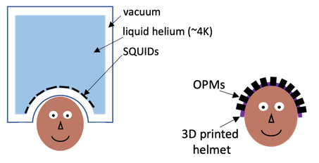
Figure 3: Schematic representation of conventional MEG system using LTS SQUID sensors (left) compared to a on-scalp MEG system using OPM sensors (right)
Fixing the support structure to the subject’s head (as in the case of a flexible cap) instead of to a chair or other large structure allows the subject to move their head, increasing subject comfort and enabling new types of experiments that were previously only possible with EEG. Moving the sensors however adds additional demands on the magnetic field compensation as movements in even a small magnetic fields create large artifacts.
Sensors - HTS SQUIDs
High temperature superconductors (HTS) are a group of materials that achieve superconductivity at significantly higher temperatures than conventional superconductors. Yttrium barium copper oxide (YBCO), for instance, becomes superconducting at ~92 K (~-180 °C). While this is still very cold it brings two major advantages: HTS SQUIDs can be cooled by liquid nitrogen (~77 K; ~-196 °C) – a much cheaper and more sustainable alternative to liquid helium – and the vacuum insulation can be decreased to as little as 1 mm. The latter makes HTS SQUIDs a great choice for osMEG. The higher temperature of HTS SQUIDs results in slightly higher noise, which is alleviated by the signal increase from coming closer to the head.
Since the working principle is the same as that of LTS SQUIDs used in conventional MEG, HTS SQUIDs have similar high bandwidth and dynamic range. While a HTS SQUID chip is very small (~10 mm x 10 mm x 1 mm) the necessary cryostat makes systems more a bit more bulky and less adaptable compared to OPM based osMEG systems.
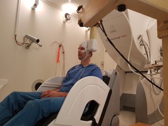
Figure 4: Photo of an on-scalp MEG recording at NatMEG using a small HTS SQUID-based system developed at Chalmers University in Gothenburg.